This page is a brief discussion of videotape systems theory, with some history thrown in for good measure. It may help give you an idea of why early videotape machines sometimes weighed upwards of a ton, and were so finicky. It also gives you some idea of what engineers had to overcome to build a machine the average person could afford!
![[Education Index 'weasel' Award.]](/eiaward.gif)
Any discussion of videotape theory would be incomplete without a brief description of the events that led to the development of the videotape recorder. As you will come to appreciate from reading this tutorial, the development of a practical videotape machine was no trivial task. The videotape machine represents perhaps, the most amazing combination of mechanical and electronic engineering that you will ever find in one device. Indeed, technology developed for the videotape machine also is fundamental to the now ubiqutious computer disk drive as well.
The first stirrings that led to a practical videotape machine happened in 1951. This is not to say that there was considerable interest in the concept of recording TV pictures before that. Indeed, ever since Jack Mullin had demonstrated practical magnetic audio recording in this country (Using two tape recorders captured from the Germans during World War II), there was also an interest in recording television pictures. (You will read later why this was so problematic.) In any case, the audio tape recorder had given life to a postwar Ampex Corporation, who was looking for a product to manufacture after it's government contract to manufacture radar components had been canceled.
Up to this point, experimentation with video recording was proceeding along two similar tracks. Both used conventional linear tape technology. One variant employed very high speeds and a single head. The other variant used somewhat slower speeds, but used multiple heads to record slices of the vast video bandwidth on separate tracks. Both approaches were plagued with severe problems that remain unsolved to this day. Two outstanding examples of this early work was the 12 channel Bing Crosby VTR, and the British VERA format.
It was in 1951 that a different approach of using a rapidly rotating head writing tracks on a relatively slow moving tape had been suggested to some people at Ampex by Marvin Camras of Armour Research. The idea looked like it had some promise of overcoming the problems associated with very high tape speeds. So, Ampex executives appropriated a small sum of money to investigate the rotating head approach. To head up the project, a television engineer by the name of Charlie Ginsburg was hired by Ampex. He remained the project leader throughout the entire project. The is the first of 'The Six' men principally responsible for the development of the videotape recorder. It was now December of 1951.
During these early days, Ginsburg had the fortune of meeting a fine young engineer named Ray Dolby (Number 2 of 'The Six'). (Yes, this is the same Ray Dolby of Dolby Noise Reduction, and Dolby Theater Sound fame.) Dolby contributed to the Videotape project in many different ways during the ensuing years. Unfortunately, Ray Dolby's quitting school (He was only 19 at the time) and joining Ampex promptly got him drafted into the Military.
Nevertheless, work on the Videotape machine proceeded. By October 1952, a working system was demonstrated. It employed 3 headed Arcuate scan, and AM video modulation. Although the pictures were hardly recognizable, they were pictures, and Ampex management continued funding the research. Shortly thereafter a second Arcuate scan machine was built, which later became known as the Mark I. This machine used a 4 headed Arcuate scan, and had it's drive motors were referenced to the AC line. A new team member, Shelby Henderson (Number 3 of 'The Six') joined on about this time as the team's modelmaker. One of his first contributions to the project was a 'female guide' to back up the tape behind the rotating head.
In June of 1953, the Videotape project was set aside while another major project was undertaken. (I believe it was the Todd-AO theater sound system) Although some work was done on the project during this time, very little was really done until August of 1954. Even so, some 'back room' efforts led to major progress in overcoming some of the problems of the videotape recorder. Enough progress was made, that a request for some quality time to work on the project was made. This was granted in August of 1954. The first task at hand was to try to improve the motor control system. This task was shared by Charlie Ginsburg, and a new team member named Charles Anderson (The fourth of 'The Six'). The results were very encouraging, and a demonstration of the Mark I to management resulted in a full go-ahead on September 1, 1954. The race was now on in earnest.
Shortly thereafter, the arcuate scan system was abandoned in favor of the transverse scan system. (The various scanning systems are explained in detail later in the tutorial.) An improved AGC system was developed for the AM video. It was also around this time that two other key members of the project came on board to join Ginsburg, Anderson, and Henderson. These new members were Fred Pfost and Alex Maxey. (#5 and #6 of 'The Six.)
The first problem encountered with transverse scan was keeping the video heads in one piece. There were at that time, only six handmade heads in existence. These heads had been used in the arcuate scan mark I. They also worked with the transverse scan head system. However, no new head designs would work in the new scanner; they kept flying apart. This would be a problem for a number of months to come. Still, armed with the new scan system and the old heads, a demonstration was made of transverse scan in December of 1954.
Although the new scanning system showed much promise, the AM AGC continued to be a major problem. (An early AM picture) No easy fixes were to be had. It was at this time that Charles Anderson proposed using vestigial sideband FM instead of AM. This was tried, and the results were extremely encouraging. It was also at this time that Ray Dolby finally got out of the military. Not wishing to repeat the mistake he has made 3 years earlier, he returned to college and worked part-time for Ampex. He simplified the FM electronics for the video signal system, which also resulted in a considerable performance improvement. (Anderson's original design was like an FM superhetrodyne radio. Dolby's design did all the processing at baseband.) First FM pictures. An early March 1955 demonstration to Ampex executives was very convincing. A goal was set at that time to have a commercial product ready in a year. (No, Time-To-Market is not a new concept!) The VTR breadboard at that time was known as the Mark II.
Another major breakthrough made about that time involved correcting timing errors in the video that resulted from the segmented scanning approach. Alex Maxey conducted a series of after-hours experiments and determined means byw hich these problems might be solved. Out of this experimentation arose the idea of moving the female guide shoe in and out to correct this problem. This method has some other unexpected positive benefits, and eventually became the accepted means of correcting these timing problems.
Fred Pfost worked during this time on solving the problems with the construction of the video heads. He solved many of the problems associated with the construction of the heads, and came up with a sandwich design that was easily reproducible.
As 1955 wore on, improvement were made in the signal system electronics, slowly extending the usable video bandwidth and improving the signal-to-noise ratio. Improvements in the servo system made the picture stable enough that it could be reproduced on any TV monitor. It was not long before good pictures from this prototype machine, the Mark III, were commonplace.
The Mark III was an ugly machine. It consisted of a crude wooden cabinet, with a top plate, and electronic chassis scattered here and there. There were also two partially-loaded racks of electronics associated with the machine. In late 1955, Ampex management suggested that the machine could benefit from a makeover. After all, this machine was going to be extremely expensive. So, Charles Anderson developed the Mark IV videotape recorder, wideotape recorder, with it's console and compact, internal electronics. It was also decided at this time to set a goal of doing a demonstration of the videotape machine at the April 1956 NARTB (Now NAB) convention.
In February of 1956, a demonstration of the videotape machine was made to about 30 Ampex people. The demonstration was so successful that the VTR team was given a standing ovation with 'Clapping and shouting that shook the building'! Over the next few weeks, leading up to the convention, a number of top broadcast engineering people were shown the videotape machine. The interest shown by these people during their visits convinced the team to finish the Mark IV, and send it to the NARTB show.
The Mark IV was finished, and several improvements were made. Work continued nights and weekends to prepare for the big show. Finally, the machine was broken down into many pieces and shipped to Chicago. Meanwhile, the Mark III was given a cosmetic facelift, and prepared for demonstration to the press in Redwood City, CA. (Home of Ampex). This demonstration was to take place the day the NARTB convention opened in Chicago. Unfortunately, this machine developed severe problems just before the NARTB team left for Chicago. A team (Headed by Ray Dolby, I believe) was left behind to fix the Mark III, and the rest headed for Chicago.
When everything was put back together in Chicago, the Mark IV was making the best pictures it had ever made. However, some CBS engineers said, predictably, 'It isn't good enough'. So, two feverish days of tweaking followed, and the performance goals were met. This was also aided by the delivery of some tape samples that were the best yet seen. (The development of these tape samples by 3M is another interesting story!) Meanwhile, the Redwood City crew solved the problems with the Mark III. All was now ready for the demonstration, both to take place on the opening Saturday of the NARTB convention.
The demonstrations, first for the CBS affiliates meeting, and then the general convention delegates was a bombshell. The Redwood City demonstration was a complete success as well. As a result, Ampex was flooded with orders. It is said that some orders were even taken on napkins! In any case, the videotape machine was an instant, astounding success!
The first production machines to be built were called the VRX-1000. Sixteen of these were handmade while a large assortment of technical bugs were worked out of the machines. One of the real problems during that time was finding suitable tape for video recording. Much effort was put into developing test procedures to determine if a given type of tape was acceptable. (Tape quality continues to be a problem, even to this day.) Another problem was manufacturing video heads in reasonable quantities. Last, but not least, everything had to be made completely reliable. (Alexander Poniatoff, founder of Ampex, told his engineering people 'I want all our products to be as reliable as refrigerators'. He made them design reliability into everything Ampex made. The result is audio recorders built in the '50's are still in routine use today.) Many people worked 30 hour days during that time to make sure the new videotape recorder was a product living up to Ampex's reputation. (Here is a picture of the Six man team responsible for the first practical VTR, posing with the Mark IV. L to R: Fred Pfost, Shelby Henderson, Ray Dolby, Alex Maxey, Charlie Ginsburg, Charlie Anderson. Here is a picture of Charlie Anderson taken in late September 2000.)
The first on-air use of videotape occurred on November 30, 1956. The event happened at CBS Television City in Hollywood, CA. The videotape recorder was used to tape delay 'Douglas Edwards and the News' three hours for the West Coast airing of the show. (Screen shot) Other networks quickly followed suit. Incidentally, the VTR used for this broadcast is now in the Smithsonian institution.
The production version of the XVR-1000 became the VR-1000. Several variants of this machine were developed, and it had a long production life.
This history would not be complete without mentioning the parallel development of the helical scan format. (Here is Alex Maxey working on an early helical scan VTR prototype. Although timebase error problems with the format could not easily be solved, Ampex managed to produce a workable machine in 1961. This machine, the VR8000, never saw it to production. However, two of these machines did make it into the hands of customers. The frame of the VR8000 became the mechanical basis for the VR1100 quad machine, and the later VR2000 and VR1200. The next helical machine I know of is the VR1500, a very early attempt at a consumer VTR. It appeared in the 1963 Neimann-Marcus Christmas Catalog. It had a price tag of only $30,000!
In any case, enough history for now. The history will continue later on in this tutorial, sprinkled throughout the theory as the technology unfolds.
Magnetic recording is a fairly new technology, with the first machines appearing just before WW2. The first machines recorded signals on a thin iron wire; wire recorders are actually still used today as data recorders on aircraft. (The 'black box'.) But, magnetic tape came into use around the end of the war, and gave better results. Germany was a big pioneer in this area.
If you take a tape, and coat it with magnetic material, you can record information on it by moving the tape past an electromagnet. This electromagnet is oriented so it's magnetic gap is completed by the magnetic coating on the tape. This leaves a pattern of magnetization on the tape. If you now run the tape that was just recorded over the electromagnet again, the magnetic field on the tape will induce a small voltage in the electromagnet. This signal is amplified, and should be a duplicate of the original signal. This sounds very simple to do, but in fact is not so easy. Let's examine why.
It was quickly discovered that you can't just apply an audio signal to the electromagnet (called a head) and expect good audio when you play the tape back. Indeed, it will be highly distorted. The reason is a property of magnetic materials called hysteresis. Hysteresis is the property of a magnet that keeps it magnetized. In order to magnetite a substance, or change the magnetization of an already magnetized substance, you have to apply a certain level of magnetic field before the change will occur. The solution to the hysteresis problem turned out to be the application of a high power-high frequency (5 or more times the highest frequency you will be recording. For audio, this should be 100 kHz or more.) signal to the head that has been amplitude modulated by the audio signal. The high frequency signal is called bias. The bias signal contains the energy needed to overcome hysteresis, and the audio modulation causes the the residual magnetism left behind to vary in step with the original signal. After hysteresis has been overcome, the amount of varying signal needed to leave a signal on the tape is very small. It is not unusual to apply 100 volts p-p of bias to a record head with just a couple hundred millivolts of audio riding on it!
The amount of bias required for a good analog recording is very critical. It varies from brand to brand of tape, and even from tape to tape in a lot. This is why some modern cassette decks have a front panel bias control. Bias affects record level, frequency response and distortion in a relationship too complex to discuss here.
The other factor that affects the amount of information that can be recorded on a tape is wavelength. The shortest wavelength that can be recorded on a tape is one that is slightly more than half the width of the gap in the head electromagnet. Although magnetic particle size and coating thickness also affect the shortest wavelength that can be recorded, it can all but be ignored for purposes of this discussion. So, there are two things that can be done to increase the highest frequency (shortest wavelength) that can be recorded on a tape: 1.) Speed up the tape so the short wavelengths are made 'longer' on the tape, and 2.) Make the head gap smaller.
The maximum tape speed is limited by mechanical considerations. It is difficult to transport tape smoothly past a head at high speeds. It also causes the amount of tape needed for a given recording time to increase. For audio, the practical maximum speed is 30 inches per second (ips).
Physics limits the narrowness of the head gap. The smaller the gap, the larger the energy needed to leave the same amount of magnetization on the tape. There is a practical minimum, but it is not a serious problem for audio, where tape speed is a bigger problem. It is, however, a problem for video.
Another problem with analog magnetic recording is that the output of the head increases with frequency at a rate of 6 dB an octave until limited by the head gap width. This is because a rapidly changing magnetic field induces more energy into a head than a slowly-changing one. This limits the low-frequency response to a certain minimum value. To compensate for this effect, equalization is required on playback (And a little on record) to flatten out the frequency response. But, you may ask, why does it seem high frequency response is the most important parameter for an audio recorder, if the head output increases with frequency? The answer is, head gap wear, dirt, misalignment, and overall losses have a much more profound effect on highs than on lows. This is true even though the high frequency signal output at the head is many decibels higher than the low frequency response.
The last consideration for magnetic recording is head-to-tape contact. The head must be in intimate contact with the tape in order for everything to work right. The output signal from the head drops at a dramatic 1 dB for every 2.2 microns of separation from the tape. (At 9MHz, a video RF frequency.) Even a small gap between the tape and head is intolerable. This is why the heads have to be kept clean in any magnetic recorder!
High fidelity audio requires a bandwidth of about 20-20,000 Hz. This represents a frequency range of about 10 octaves. (An octave is a doubling in frequency.) Video requires a range of 30 Hz-4.2 MHz for broadcast quality, a range of 17 octaves. Due to the problems mentioned previously, it is just possible to accommodate the ten octaves of an audio recording using traditional techniques. Some very carefully designed audio recorders might be able to squeeze out an extra half-octave or so, but this is the limit.
As previously mentioned, you can either speed up the tape, or reduce the gap width to increase the shortest wavelength you can record on tape. However, there are still limits that need to be overcome. Mechanical stability becomes a serious problem at very high tape speeds, as well as huge reel sizes. It was once calculated that a longitudinal videotape machine would require reels seven feet in diameter to hold the tape for one hour of recording time! 30 ips still remains a practical upper limit.
There was still some latitude left in gap width to play with. It was determined that the minimum practical gap width was about .89 microns, a very small value. Even with this narrow a gap, a tape speed of 1000 to 1500 ips was needed to record full bandwidth video!
In any case, a practical videotape recorder using traditional longitudinal (I.e. tape passing in front of a fixed head) did not seem possible, even with the smallest practical head gap. Nevertheless, a couple experimental machines were built, which would record a few minutes of marginal-quality video onto 1/4 inch audio tape. One surviving example can be found at the Ampex museum of magnetic recording, in Redwood City, CA.
The solution to the tape speed problem came when someone suggested moving the head past the tape rather than the tape past the head! The idea was to use a revolving head array that would record information on the tape in the form of tracks. On playback, you would scan the tracks with the head array, and recover the information. Although this turned out to be a very complex process, it was and still is the best solution to recording wideband information such as video or data.
Three scanning systems were initially proposed. Arcuate scanning used 2 inch wide tape that passed under a spinning disc with three (later four)heads mounted on one side. It left arc-shaped tracks on the tape. Although this was the simplest approach to scanning the tape, it could not be made to work reliably. The second method tried was Transverse scanning. Here, 2 inch wide tape was formed into a 'U' shape, and a disc with four heads on it's edge would scan the tape while it was in the 'U' shape. The disc was perpendicular to the long dimension of the tape, so it left nearly vertical tracks on the tape. It worked, and at the time, showed the greatest promise. The third system was called Helical scan, and involved wrapping tape around a cylinder at an angle. A disc with one or two heads on it would scan the tape through a slot in the cylinder. The wrap angle of the tape was selected so the head would scan long, diagonal tracks on the tape. Although it was simple, and showed a lot of promise, helical scan was not quite good enough yet for a practical videotape recorder. It also required a very complex tape transport, as the tape had to be wrapped around the cylinder at a very precise angle. The other two scanning methods had essentially straight-through tape paths.
One of the interesting things about magnetic tape is the shape of the magnetic particles on the tape itself. They tend to be spindle shaped, not round as you would expect. It was found early on in the history of magnetic recording that the magnetic particles work best when their long axis is oriented along the direction of the head gap motion. This quality of a magnetic tape is called it's Magnetic Orientation. Therefore, the particles are aligned along the long axis of most magnetic tape, including that intended for use with helical scan VTR's. However, if tape was to be used with a transverse scan VTR, it had to have it's magnetic particles aligned at right angles to the long axis of the tape. This requirement doesn't add a step to the tape manufacturing process; all that needs to be done is rotating a biasing magnet 90 degrees. This magnet lines up the particles on the tape at a point that the still-wet binder permits the magnetic particles to move around. One of the undesirable side effects of this is that tape manufactured for use with transverse scan VTR's is not useful for anything else! Very late in the life of quad, Fuji introduced a tape that had longitudinal particle orientation in the longitudinal track areas of the tape, and transverse orientation in the video area. Although this tape produced superior results, it was very hard to make. Thus, it's substantial extra cost prevented it from catching on.
Transverse scan was chosen for the first practical videotape recorder. The two inch wide tape moved past the headwheel disc at 15 ips. The head rotated at 14,400 revolutions per minute, or 240 revolutions per second! (NTSC)(15,000 RPM or 250 RPS in 625 line systems.) The diameter of the head, and the radius of the shoe that held the tape in a 'U' shape were chosen so that at least one of the four heads would be in contact with the tape at any moment, and one head would come on to the tape just before another head left contact with the tape. This overlap allowed the recording of an uninterrupted signal on the tape.
A 240 Hz sine wave was direct-recorded on the lower edge of the tape. The phase of this signal was such that it could be used to determine where the tracks are actually recorded on the tape. This is called the Control track Audio was recorded along the upper edge of the tape. A second audio track was recorded between the control track and the tape edge. This track was used for cuing purposes and is called the Cue track. After allowances for the audio and control tracks, the center of the tape contains nearly vertical tracks that each hold 16-17 TV lines of information, with allowances for overlap. 960 of these tracks are laid down every second, and 57,600 every minute! (A NTSC TV picture Frame has 525 lines in two groups of 262 1/2 lines each, which are called Fields. Each line on the screen is scanned every other field. In the first field, all the odd numbered lines are scanned. In the second field, all the even numbered lines are scanned. There are 15,734 lines scanned every second, 59.94 fields scanned each second, and 29.97 complete frames every second. These are really odd numbers, and there is an equally odd story on how they came to be that way, but that's a story for another time. The process of splitting a TV frame up into two fields is called Interlaced Scanning and is employed in all major analog TV systems in use today. Many digital TV systems scan all the lines in one pass for each frame. This is called Progressive Scan.)
The effective speed of the video head was now about 1551 ips, or about 129 feet per second. (Or about 88 miles/hour!) This easily solved the upper frequency limit problem. Unfortunately, a number of new problems were created by this scanning process, and each of them required substantial engineering to overcome.
The first of these problems was low frequency response. If the output of an audio head was at a given level at 20 kHz, the same signal would be some 60 dB lower at 20 Hz, due to the aforementioned 6 dB/octave increase in playback level with frequency. For audio, 60 dB can barely be compensated for with simple electronics. For video, a signal recorded at 30 Hz would be 102 dB lower than one recorded at 4.2 MHz. This is more than a 10 billion:1 change in level over the 17 octaves of the video signal! No equalizer known then or now could easily correct this sort of a gain imbalance. The practical symptom caused by this imbalance was noise in the picture.
So, the engineers knocked their heads together again, and came up with FM recording. The process was simple: Convert the video to FM with a carrier frequency situated near the top limit of the frequency response. The primary advantage was to shrink the bandwidth required to reproduce the full range of video frequencies down to about 10 octaves (with FM sidebands). Another important advantage of FM is the reduction of high frequency noise in the picture. AM modulation would have left more noise in the picture at high frequencies, where it is more objectionable to the eye. FM recording does not require bias, as the signal is constant-amplitude, and recorded at the saturation level of the tape. It acts as it's own bias. Amplitude variations resulting from tape imperfections could be removed with a simple limiter. But even FM wasn't without problems, as we shall see.
The FM frequencies originally chosen for quadruplex were 4.28 MHz for sync tip, 5 MHz for blanking, and 6.8 MHz for peak white. This combination gave excellent black and white pictures. But when color started to be popular, this combination caused a strong beat between the color subcarrier and the FM carrier. So, a second scheme of frequencies had to be adopted. These were 5.5 MHz tip of sync, 5.79 MHz blanking, and 6.5 MHz peak white. This eliminated the beat problem, but degraded the signal-to-noise ratio. Finally, a third standard was created when better electronics, heads and tape were available to take full advantage of the quadruplex format. This format features a sync tip frequency of 7.06 MHz, blanking at 7.9 MHz, and peak white at 10 MHz. This format came to be known as High-Band. It gave excellent color along with low beat interference and good signal-to-noise ratio. (The older standards came to be known as low-band mono and low-band color, respectively.) High band was so good that it was adopted for 1" type C. Yet, at the end of the quadruplex era, a standard known as super high band was briefly introduced. It used frequencies as high as 11.7 MHz, but had a low deviation, like low band color. although it offered superior color, it never caught on due to it's noticeably poorer signal-to-noise ratio.
Virtually all VTR formats have been 'high-banded' at some point in their careers. Notable exceptions to this are 1" type C and VHS. (VHS HQ is actually a series of specification-tightenings.)
We have figured out how to record and play back the video signal. Now, we need to be able to find it on the tape. This is a job for the servo system. The servo system, at minimun, consists of a drum servo that controls video headwheel speed, and a capstan servo that controls linear tape speed.
In order to play back a scanned track on a piece of tape, we have to lay the track down at the right place on the tape during recording. The actual track path is determined by mechanical guiding of the tape past the head. The speed of the video headwheel must be held constant at the correct speed to produce consistent, repeatable tracks, and to preserve timing accuracy of the recorded sync information. (Sync, or synchronizing information in video is pulses present in the signal to denote the beginning of lines or fields. The timing accuracy of sync is very critical, as we shall see later.) The speed of the tape past the heads must be held constant to keep the tracks at the correct angle, and allow the video heads to scan down the middle of the tracks during playback. The servos serve to keep everything constant at the correct speeds during recording. The servo system also generates a signal that is recorded on a longitudnal track on the tape, called the control track. The control track serves as a refrence for the servos on playback, so the tracks can be found on the tape.
During playback, the servos are much busier. The drum servo is looking at the timing of vertical sync, and adjusting it's speed to keep it constant. The drum servo also has to adjust headwheel position to start scanning a video track at it's beginning. The capstan servo looks at the control track pulse, and adjusts tape speed to put the video tracks under the rotating video heads. Building a good servo system is more challenging than building a good video signal system. The servo system has to lock up quickly when playback is started, and then keep locked for the duration of the tape. If the drum servo becomes unlocked, the picture quality will deterioate, and the picture will appear to get narrower or wider, often alternately. If the capstan servo becomes unlocked, the picture will alternately go to noise and come back.If severe enough, the picture may break up entirely.
Early servo systems required constant adjustment, and became tempremental even if the room temperature changed. Modern electronics fixed these problems, and today most servos are actually digital approximations of analog circuits. The advantage of the digital servos is that they can lock up faster, and they don't drift.
There are other servo systems in some videotape machines. Quadruplex machines have a vaccum guide shoe that forms the tape into a 'U'. This guide needs to be moved in and out to minimize timing variations that occur between scans. If uncorrected, guide position error leads to a condition called banding. Banding is seen in the picture as a series of horizontal stripes spaced evenly. It is most apparent in areas of saturated color. This error can be automatically corrected for by measuring the timing error in the horizontal sync, and adjusting the guide position to minimize it. This servo is called, appropriately enough, the guide servo.
Most better machines made today are capable of precision shuttle, slow motion, editing, etc. In order for these features to work properly, the tape must be at the proper tension at all times. The reel servo system does this by adjusting the speed of the supply and take-up reels to keep the tape properly tensioned. Until the advent of microprocessors, reel servos tended to be very complex. They were also very challenging to troubleshoot because some servos had half a dozen or so feedback loops!
Most tension servos do not really measure tape tension. They actually measure the position of a moving guide, which is under spring tension. The spring actually determines the proper tension. All the servo does is try to keep the guide in the same spot all the time. If the guide is in that spot, the tension is enough to balance the force of the spring, and tension is held constant.
One very interesting tension servo was used in the Ampex AVR-1 (Quad) and the IVC 9000 (Helical) VTR's. In these machines, the tape came off the reel and entered a Vaccuum Column. There, vaccuum pulled a loop of tape into a long box whose height was just high enough to fit the tape. A series of lights were mounted on one side of the box, and photocells on the other. The loop of tape would cover some of these, and tell the servo system how much tape was in the column. Enormously powerful reel motors could control tapr reel-off precisely enough to keep just the right amount of tape in the columns. A similar system was employed on the take-up side to control spooling of tape onto the take-up reel. The system worked extremely well, and was one of the few reel servo systems that allowed mixing many different sizes of reels. It never caught on because of it's mechanical complexity and the powerful vaccuum pump needed to evacuate the columns. This concept was borrowed from computer tape drives of the time.
Some professional videotape machines are capable of noiseless slow motion. Remember that the track pitch on the tape is a function of head scanning AND tape motion. Stop the tape motion, and you will scan two or more tracks with the video head. Wherever you cross tracks, you get a Noise Bar in the picture. This also occurs in shuttle, where the tape speed is too high, or in the wrong direction for proper tracking. In shuttle, you usually see several noise bars. But, how do they get rid of noise bars in slow motion?
In consumer machines, there is a special circuit in the capstan servo that can center the track under the video head. In consumer formats, the heads can just about stay on a track in still, provided it is centered properly. The slower the normal tape speed, the better this works. This is why the slowest speeds on your beta or VHS machine produce the best still and slow effects.
In professional machines, the high tape speeds and the wide Guard Band (The unrecorded space between tracks, which is almost nonexistent in consumer machines.) make any kind of 'centering' scheme unworkable. (Although some early machines had a mechanical scheme of varying the angle of the tape across the heads in still, to give a better still picture.) So, a servo system was developed that measures the amount of signal coming from the video heads, and adjusts the position of the heads to follow the tracks. The position adjustment is done by mounting the head on a piezoelectric bimorph, which bends when voltage is applied to it. By adjusting the amount of bend as the head scans the tape, the track can be properly scanned in still or even reverse play. Typical speed ranges over which a system like this is effective is 1 X reverse to 3 X forward playback. The servo system responsible for doing this is called Automatic Scan Tracking (AST)(Ampex) or Dynamic Tracking (DT)(Sony). This system is not seen in consumer machines because the bimorph assembly is extremely difficult to manufacture, and the electronics are very complex. A high voltage supply is also required (+/-250 volts) which must be connected to the rotating head via slip rings. The one exception to this is the European Video 2000 format, which has a head-moving servo. This consumer format also has a number of other unique features. AST was developed by Ampex engineers Dick Hathaway and Ray Ravizza.
An equally complex magnetically operated head-moving system is also used in some machines, notably some of the digital VTR's.
Recently, some VTRs have been appearing on the market that use digital reconstruction of the broken-up picture to create a slow motion similar to AST. While costing far less than AST-equipped machines, and also having similar control-feel, their picutre quality is not nearly as good.
JVC has recently released a consumer VHS machine with a feature called 'Dynamic Drum'. This feature is also proported to be present in some of their professional D-9 (Digital-S) machines. This system slightly tilts the entire video head drum assembly to improve signal recovery in non-standard tape speeds.
The mechanical requirements of a videotape machine are very severe, and it is a triumph of modern manufacturing that they could be mass-produced at all. We will now look at some of the mechanical engineering problems that had to be overcome to build a videotape machine.
The heart of a videotape machine is the video head assembly. It has undergone a lot of changes over the years. In the early days, the quadruplex headwheel was turned at 14,400 RPM by a polyphase AC motor. It used ball bearings, and slip rings to get the signals to and from the rotating heads. Precision machined parts were used to guide the tape and form it into the correct 'U' shape so it could be scanned by the heads. Vaccuum was applied to the inside of the guide to pull the tape into alignment. The guide could be moved in and out, as well as up and down, to correct timing errors. On many machines, the in-out motion was under servo control. The video heads themselves were originally made of Alfesil (Also known as sendust.). Newer heads, as well as all modern heads, are made of ferrite.
The first problem encountered with the quadruplex video head was a particular form of video distortion known as the waterfall effect. It looked like a waterfall in the background of the picture. The problem was traced to tiny abnormalities in the ball bearings used in the head. No matter how carefully the bearings were manufactured, they would eventually wear in such a way that they would develop a vibration. This vibration was coupled to the video headwheel, and caused tiny timing variations. These vibrations would occur at the rate the ball cage turned in the bearing, so it caused the noise pattern to run down the picture. The solution was to eliminate the ball bearings, and replace them with air suspension bearings. Now, quad videotape machines required a fairly hefty compressed air source to operate the air bearings. The presence of compressed air in the machine eventually led to a wide variety of pneumatic systems in other parts of the machine.
The second major problem encountered with the quadruplex head was brush noise in the picture from the slip rings. The solution to this problem was most ingenious: the development of rotary transformers. Concentric coils of wire were mounted in grooves on a ferrite disc. One of these would be fixed, and the other would be on the rotating headwheel. They were spaced as close as possible so the magnetic fields would couple. Rotary transformers can be used to bring any kind of high frequency AC signal to the heads, and have left little to improve upon since their inception.
Quadrature error on a quad head was a timing error produced by the fact that the heads were not exactly 90 degrees apart. It produced a stubborn timing error that could only be corrected by physically adjusting the position of the delicate heads. Today, the same error exists in helical scan heads, and is called Dihedral. Modern professional machines can have five or more pairs of heads on the headwheel. Manufacturing techniques have improved to the point where dihedral correction isn't even available as a field adjustment.
Running very weak signals from a video head to a preamp that may be a couple feet away caused a lot of performance loss in early VTR's. With miniature tubes, and later transistors, manufaturers were able to build the preamp inside the head assembly, just after the rotary transformers. Ampex marketed one version of their quad head assembly, the Mark 10, with three different optional preamp modules: None at all, Tube, and Solid state. Any head could be converted to another type just by changing preamp modules. Thus, an older machine could be retrofitted with a better head by simply replacing the assembly with a new one containing the correct module. The last improvement, only seen in helical scan machines, was to move the preamp right on to the headwheel itself. This provided the best signal-to-noise ratio. However, slip rings are again required to bring power and control signals onto the rotating headwheel. The actual video signals go through rotary transformers. Because of the expense of slip rings and miniature high-G relays (The centrifugal force on the inside of a 1" type C video head is 1,000 g's!) for record/play switching, this is rarely seen in consumer machines.
In the early sixties, helical scan machines began to become practical as the engineering problems they presented were solved. They did not require air bearings, as their rotational speed was much lower (1800 to 3600 rpm vs 14,400 rpm.). But, they had problems of their own.
In the quadruplex format, the length of tape that needed to be precision guided was about 3/4 of an inch. Furthermore, vacuum served to hold the thick tape in proper alignment. In helical machines, it was required to hold a piece of tape as long as 16 inches in an angle wrap around a cylinder. This tape had to be in precisely the correct position for it's entire length, and lie flat on the surface of the cylinder. The tendency towards thinner tape made this even more difficult. The solution was very complex. Many precision guides were used to put the tape at the right angle to follow the head drum. It is not unusual to encounter guides that were mounted at strange angles, and have tapers or steps on them as well. A precision guide, called a Rabbet Guide was built into the lower part of the head drum cylinder. The tape lightly rests on this guide as it wraps around the head drum. Finally, the head drum assembly itself is usually mounted at an odd angle to facilitate tape wrapping around it. Open reel helical machines often have the reels at different heights to eliminate a lot of the oddly angled guides. Obviously, you can't easily do this with a cassette!
Another development that came with newer helical scan machines is azimuth recording. As the need for longer playing times pushed tape packing densities higher and higher, the narrow guard band between video tracks shrank until the tracks practically overlap. All of the newer formats use two-head, 180 degree wrap helical scan. This means that every other track is recorded by every other head. Since the adjacent track was recorded by another head, introducing a deliberate azimuth error between the two heads means that the track recorded by head 'A' cannot be read by head 'B'. The azimuth errors designed into modern heads varies between 7 and 14 degrees, meaning a 14 to 28 degree azimuth error between tracks. As a result, there is very little crosstalk between tracks, even though they practically overlap. This system is called, oddly enough, azimuth recording.
All videotape stretches a little while in use. The specifications for each videotape format specify how much tension needs to be on the tape for proper take-up without damage. They also specify how much holdback tension needs to be applied from the supply side to maintain proper tension around the head drum. (Tape tension wasn't nearly as critical for quadruplex.) All but the top-of-the-line professional studio decks tend to use a somewhat primitive holdback tension brake. A felt band is wrapped loosely around the supply reel table, and is connected to an arm which rests against the tape. If the tape tension drops, the arm moves inward against the tape. This inward motion tightens the felt band through a linkage, and restores proper tension. Conversely, if the tape tension gets too high, the tape pushes the arm out, and the band is loosened through the linkage. As crude as it sounds, this system is quite reliable. Top-of-the-line machine detect tape tension through sensors, and the reel servo makes the correction.
Cassette-based machines need some way of pulling the tape out of the cassette, and wrapping the tape around the head drum without operator intervention. Special quadruplex machines, called spot players, were built to specifically play back commercials during commercial breaks. These machines used small cassettes that could contain up to five minutes of tape. Puffs of air were frequently used to pull the tape into it's proper position. The straight path of the tape, along with a retractable vacuum guide on the video head, made threading straightforward in these machines.
Helical scan cassette machines posed a major problem. The tape had to be wrapped around a cylinder, and past a number of fixed guides and heads. Sony provided the first solution, by using a ring that pulled a loop of tape around the video heads and the rest of the guides. The system was simple and worked well. Sony also came up with another method: Two tape guides were mounted on moving tracks, and pulled the tape out of the cassette, and around the video head. They couldn't get this to work well, and abandoned the idea in 1966. JVC quietly bought the patent to that threading system and used it for the first time in a machine called video home system, or VHS! The ring threading system was simple, and Sony owned the patent on it. The M-load system, as the moving guides system came to be known, was hard to manufacture, and required excessive tape tension. But, they didn't have to buy rights to use it from Sony; JVC already owned the rights. Interestingly enough, many professional machines built by Sony today use the M-load system, while the corresponding machines built by JVC and Panasonic use the ring load system!
There are many other mechanical systems in a typical videotape machine, but they don't differ from an audio machine or they didn't pose a severe design challenge. They will not be covered here.
We will follow the video signal as it takes a trip through the signal system of a typical direct color videotape machine, such as quad or 1" type C. The variations on this theme will be discussed separately.
Video enters the VTR electronics through an input buffer of some sort. Here, manual or automatic video level control is applied to correct for level variations in the video. The video is then low-pass filtered and run through a pre-emphasis network. The pre-emphasis boosts the high frequency components. of the signal, and results in an improved signal-to-noise ratio. After being black and white clipped to prevent overmodulation, the video is applied to the FM modulator. The FM signal is called RF from here on in, because it is well up into the radio frequency range. A sample of the RF is sent to the playback electronics. this signal is called the electronics-to-electronics or E-E signal. The E-E signal is used to monitor input video, and make level adjustments.
The RF signal is sent to the record amplifiers, which boost the signal to a level necessary for recording. The signal applied to the heads during record is usually fairly hefty, due to the high frequencies involved, the narrowness of the head gap, and the high coercivity of modern tape. The signal from the record amplifiers passes through the rotary transformers and on to the video heads.
Playback isn't as simple. The low-level signal from the video heads is coupled through the rotary transformers to the preamps. The preamps boost the very weak signal, and compensates for head resonance, etc. The signal from each preamp is applied to the switcher, which selects which head is playing back at that moment. The switching signal is developed from sensors that determine what rotational position the video head is in.
The switched RF is now applied to the equalizer. This is perhaps the most interesting step in the playback process. Equalization of the RF signal controls high frequency of the baseband video signal. Because the phase linearity of FM signals in this application is critical, ordinary filters cannot be used. They tend to introduce Group Delay, an ineqauity in signal delay through a circuit between the low and high frequencies. Instead, a Transversal filter is used. A transversal filter shapes frequency response by mixing a signal with one or more delayed versions of the same signal. The phase addition or cancellation alters the frequency response without introducing group delay. This circuit is often called a Cosine Equalizer or Comb Filter. Sometimes, more than one equalizer is used in series. The second equalizer often has adjustable response that changes for each head.
After equalization, the RF signal passes through a switch that selects either playback or E-E RF. After this, the RF now splits into two paths. One path goes into a delay line with a delay of one horizontal line, to a switch. The other path goes directly to the switch, and is the normal path. A level detector senses any drops in the RF level that would indicate a Dropout. A dropout is a momentary loss of RF caused by a defect in the tape coating. If a dropout is detected, the switch is thrown, and RF from the previous line replaces the dropout. In many professional machines, the dropouts are only detected here. The timebase corrector does the actual dropout fix.
After dropout compensation, the RF enters the limiter. After passing through several stages of limiting to eliminate all traces of AM, the RF is applied to the demodulator. The demodulator is usually a pulse-counting FM demodulator. After demodulation, the video passes through a low-pass filter to eliminate any residual RF. The video is then de-emphasized in a network that is opposite of the pre-emphasis network.
After an optional AGC stage, the video is ready for the outside world, which usually involves a processing amplifier and timebase corrector of some sort. More on that later.
Direct color systems, like the one described, are simple and produce high quality recordings. However, mechanical instabilities make the output signal too 'jittery' for color. The mechanical instabilities introduced by a videotape machine are called Timebase Errors. The usual way this error is corrected is to use a Timebase corrector or TBC. These very complex devices are discussed later.
Timebase correctors are too expensive and complex to put into consumer machines, although this is slowly changing. Another means to correct the chroma jitter was needed that would not require thousands of dollars in electronics. The solution was a system called Color-Under. In the color-under system, the chroma (color) information is separated from the luminance (Black and white), and down-cnd white), and down-converted to a lower carrier frequency. (Chroma information is suppressed-carrier analog quadrature AM centered at 3.579545 MHz in NTSC.) This signal is recorded as an AM signal below the FM luminance information carrier on the video tracks. On playback, the luminance timebase error is measured, and the chroma is converted to the correct frequency with the jitter corrected. Some loss in chroma frequency response is incurred in this process.
After the video input buffer, the chroma information is separated from the luminance information with a filter of some sort. In newer machines, this is often a Comb Filter. (A comb filter is a type of transversal filter that separates luminance and chrominance by using delayed video from the previous line. It takes advantage of the phase reversal that the chroma carrier experiences every horizontal line. More on this later.) A Voltage Controlled Oscillator (VCO) is locked to horizontal sync, and runs at some multiple of horizontal sync, such as 40 X Fh. A second crystal oscillator produces a signal at the color subcarrier frequency. These are mixed together to form a color conversion signal. Before mixing this with the chroma signal, the phase of this signal is inverted every other line, every other field. The color conversion signal and the chroma are mixed, resulting in a low frequency chroma signal. For consumer beta and U-matic, this frequency is 688.373 kHz. (43.75 X Fh) For VHS, this frequency is 629.040 kHz.(40 X Fh) This signal is recorded along with the FM luminance on the tape.
On playback, the low frequency chroma is separated from the FM luminance just after the RF head switch. This chroma is run into an AGC stage, which removes level variations due to head wear, etc. The 40 X Fh VCO is locked to playback horizontal sync. This compensates the the color conversion signal for horizontal rate timebase error. A second VCO creates the 3.579545 MHz color subcarrier frequency. These are mixed to form the color conversion signal. Before mixing with low frequency playback chroma, the color conversion signal is inverted in phase every other line, every other field. The low frequency chroma is mixed with the color conversion signal, and the original chroma signal results.
The burst in the recovered chroma signal is compared to a crystal oscillator running at the proper burst frequency. Any residual frequency error causes the second VCO in the color conversion signal generator to shift frequency to correct the error. Thus, all color instability is removed.
The consumer VCR formats use azimuth recording to ensure the FM luminance does not crosstalk. However, this does not work on the low frequency chroma signal because it's frequency is too low to be affected much by azimuth errors. So, there is significant crosstalk present on the chroma signal upon playback. But, remember how the phase of the color conversion signal was reversed every other line, every other field on record and playback? This causes the chroma on every other field to not reverse phase every horizontal line like it is supposed to. This is restored to normal during the up-conversion, but the crosstalk component has it's phase reversal canceled out. The crosstalking chroma is now easily removed in a comb filter. Professional formats employing color-under recording (U-matic, for instance) do not need this comb filtering system, as the guard bands on the tape prevent chroma crosstalk.
The chroma and luminance video are reunited, and the result is a color picture that is stable without a timebase corrector. The price paid? Reduced resolution in the picture due to the separation and recombination process.
It should be noted that the actual signal processing is a bit more complex than indicated here. Also, older color-under formats, such as 3/4" U-matic, which have significant guard bands between their tracks, have simpler color under circuits. Other color-under schemes have been devised and used. Many of these employ a pilot tone recorded below the FM luminance signal that is used to measure and correct the timebase jitter error.
One other circuit that is present in some newer consumer VCRs is the second noise canceler. This is yet another transversal filter that removes luminance noise by summing the current and previous line. Any high frequency information that is not common to both lines is filtered out. This removes some very objectionable noise while having little effect on detail in the picture.
Servo systems do the same thing in every videotape machine, but differ so much in design that it is hard to give more detail that what has been presented already. I will add some material that will help you understand servos a bit more.
The analog servo circuits in older machines make heavy use of a circuit called a Sample and Hold Phase detector. This circuit requires two inputs: an input pulse and a sample pulse. The input pulse starts a linear ramp generator that produces a smooth ramp with a period a bit less than the sample pulse repetition rate. The sample pulse opens a switch that charges a capacitor to the instantaneous voltage of the ramp at the moment of the pulse. The capacitor stores this voltage, which is buffered and presented to the outside world as an error signal. If the sample pulse occurs a little earlier than normal, the sampled voltage is a bit lower (Assuming a positive-going ramp.). If the sample pulse occurs a bit late, the sampled voltage is higher than normal. The error voltage is used to change a motor speed, or retune a VCO, etc.
Another circuit sometimes used for measuring error in a servo circuit was a frequency discriminator The discriminator used a special kind of tuned cirucit to measure the frequency of a signal. The output of the tuned circuit fed a pair of rectifiers. If the frequency of the signal was correct, the tuned circuit's output would be balanced, and the signals at the outputs of the rectifiers would cancel. If the frequency was high or low, the balance of the tuned circuit would be upset. The output of the two rectifiers would not be equal, and their sum would be an error voltage proportionate to the frequency error. Although not usually used directly for electromechanical control, the frequency discriminator was used to help produce reference signals from sync, etc.
Newer machines measure error by counting digitally generated pulses between the input pulse and the sample pulse. A change in the count causes the servo microcontroller (Or a special digital servo chip or chips in earlier machines.) to issue a error correction adjustment to a motor speed, etc.
The drum and capstan servos are actually two separate loops: the speed servo and the phase servo. The speed servo is usually a sample and hold type circuit that compares a motor tachometer pulse to itself through a fixed delay. When the speed is correct, the delay puts the sample pulse in the center of the ramp. This circuit gets the motor up to speed, and keeps the speed approximately correct. The phase servo compares a reference signal to a variable signal generated by motion of the controlled device, and issues a speed change to bring the controlled device into an exact state of phase lock. You could say that the phase servo knows the exact shaft angle of the motor at any given moment.
All servo systems need a reference to carry out their correction activities. During record, the drum servo uses vertical sync as a reference, and the capstan servo uses the drum tachometer pulse as a reference. This ensures these motors run at constant speed, and are locked to each other. On playback, the drum servo uses reference vertical as it's reference, and compares it to off-tape vertical. The capstan servo uses the drum tachometer as a reference, and brings the control track into phase with it. Much of this phase comparison is done using sample-and-hold circuits, or pulse counting discriminators. Some early servos, such as the Ampex Intersync also used FM discriminators to measure the frequency error of a tachometer signal.
Most modern VTR's employ some form of electronically commutated DC motor for those motors under servo control, especially the drum and capstan motors. Older machines used a variety of interesting motor control techniques, as the technology for electronically commutated motors was not yet available. Early quad machines often used polyphase AC motors, of two or three phases. Digital dividers and power amplifiers provided the sometimes substantial AC power needed to operate these motors. This made the best use of existing motor technology as no commutators, slip rings or active electronics within the motor were required.
Another popular speed control method employed a constant-speed motor driving the video head drum via a belt. The pulley diameters were chosen such that the head would rotate slightly faster than required. The belt was of special design, and could slip slightly without damaging itself or the pulleys. An iron armature was mounted on the head drum shaft, and was surrounded by a DC electromagnet. When current flowed through the electromagnet, the magnetic field would provide a braking force to the armature, and slow down the head drum. By varying the current, the necessary speed control could be effected. Servo failures in these machines were often easy to recognize, especially if the servo called for excessive slowing. There would be an unearthly screeching noise from the machine, followed by the smell of burning rubber! This scheme was known as the Drum Brake.
The last thing to mention in the servo section is the control track record/play circuit. For quadruplex, the control track is a 240 Hz sine wave on record. Since it is a direct recording, the playback signal is a distorted, double-humped signal that actually represents the rate of change of the original sine wave. A filter circuit in the servo section of the machine converts it into a clean sine wave, or a pulse. All other VTR formats I know of record a simple square wave. It is reproduced as positive and negative going spikes corresponding to the leading and trailing edges of the original square wave. Also, most professional formats record an extra pulse to denote the beginning of a new frame.
For Direct color systems, where the chroma and luminance stay together, some form of timebase correction is necessary if you want color playback. It is optional for color-under formats, but required if you want to mix the output signal with other signals in a video production switcher. Timebase correction is simply the process of removing timebase error from a videotape machine's output video. Anytime a video signal is recorded on an mechanical media such as tape, instabilities will arise in the signal caused by the mechanical imperfections of the storage device. These may not cause a problem if you are simply viewing the picture on a monitor, but they are a major problem if the signal needs to be exactly timed with other video signals. There are basically three ways to do timebase correction. We will briefly look at all three.
The first, and simplest system, the electronically variable delay line, will correct timebase errors up to about a microsecond peak-to-peak. This system is only found in quadruplex machines, and some 1 inch type B machines. It was also tried unsuccessfully with some early industrial helical scan machines manufactured by IVC and Ampex. In these formats, the mechanical system and servos had to be be extremely accurate to hold timebase errors to about one microsecond. This is one of the reasons quad was such a finicky format: there was no room for error! These systems always existed in two parts: a coarse delay line that corrected most of the timebase error, and a fine system that corrected the rest.
The system works by comparing the horizontal line period of the off-tape video to a standard. The result was a DC voltage that controlled an electronically variable delay line. This delay line was a combination of several hundred small value coils shunted to ground through several hundred varactor diodes. A DC voltage applied to the varactor diodes varied their capacitance, and thus the delay of the delay line formed of these components. The drive voltages for the diodes had to be supplied from a circuit that converted the linear error signal into a highly logarithmic control voltage. The voltage also had to be bipolar, as the varactor diodes were hooked up with alternating polarities to cancel out their nonlinearities. There was also a feedback signal to the servos to keep the signal in the timing center of the delay line. The circuits were fairly simple, but required large numbers of very expensive precision components.
The second stage of the delay line compared playback color burst to reference color burst, and generated an error voltage that controlled a shorter, faster electronically variable delay line. There is also a circuit to feed a correction signal back to the coarse delay line to keep the signal in the timing center of the fine delay line. Additional circuits were present in both the coarse and fine delay to correct errors induced in the video by the electronically variable delay lines.
When in a good mood, this system worked extremely well, and resulted in a very jitter-free signal. Ampex called the coarse and fine delays AMTEC and COLORTEC, respectively. RCA called them ATC and CATC.
Relaxing the timebase stability requirements of the mechanical portion of a videotape machine was a major goal of videotape systems designers. Indeed, videotape as a flexible (All puns intended) production tool would never really occur until the tight mechanical stability problems could be overcome. And, the bottleneck of the problem was the timebase corrector.
In the late sixties, Ampex announced a major breakthrough in the search for a timebase corrector that had a larger error window. Their solution was to correct timebase error in coarse steps, and leave just a small amount of error that had to be corrected with an electronically variable delay line. This was made possible by the availability of Glass Delay Lines.
A glass delay line, sometimes called an ultrasonic delay line, consisted of a piece of quartz glass that had precisely machined facets. A piezoelectric transducer injected a vibration into the glass block, which bounced around off the facets. After a certain delay, the vibration made it's way to a second piezoelectric transducer, which outputs a delayed version of the input signal. Relatively long delays were available, including an entire horizontal line period (63.56 microseconds).
Ampex connected a number of these delay lines in series, with the delay decreasing in binary sequence from 1/2 line on down. Below 1 microsecond, the delay line was a one microsecond fixed, lumped constant (= made of discrete components) delay line with eight taps. A small electrically variable delay line corrected the residual error, which was under 125 nanoseconds. A digital error measurement system measured the error and selected the appropriate delay lines to eliminate most of the error. Although it had some bugs, the system worked very well. However, it still required large amounts of precision electronic parts to construct. It was also a major pain to align these systems because of distortions induced by the delay lines being switched in and out. This system was present in just two machines I know of for sure, both quadruplex format: the AVR-1 and the ACR-25 spot player. (Later ACR-25's had digital timebase correctors, borrowed from the AVR-2.) Both this system and the earlier AMTEC system were developed by Charlie Coleman of Ampex.
An error window of one horizontal line was more than adequate for any quadruplex timebase error. But, it was just barely adequate for any helical scan machine. The bulkiness and complexity of the tapped-delay line system made it impractical for anything except a full-broadcast videotape machine, and it was never adopted in any helical scan machine that I know of.
At the close of the sixties, digital IC's were just starting to become popular logic building blocks for all sorts of devices. A number of engineers from around the world were working on an all digital solution to the timebase correction problem. The concept was simple: convert the video signal from analog to digital, store it in a memory, and read it out again at a stable rate.
It sounded simple on paper, but was in fact extremely difficult (Like everything else involving the videotape recorder) to actually build. It was determined that the minimum digital sampling frequency that could be used was three times the color subcarrier frequency, or 10.738635 MHz. Each sample required eight bits of data, although a few early machines tried to get by with just seven. If you wanted to store just one line of video under these conditions, you needed 683 bytes of memory. Not any memory would do, it had to be very fast. An access time of under 90 nanoseconds was required. This may not seem like much memory today, but in 1976, this was a lot of very fast memory! Even tougher was building an analog-to-digital converter that would run at 10.7 MHz. But, when the chips finally became available to build a digital timebase corrector, they did very quickly. There is a story that tells of a long line of broadcast engineers placing orders for the first digital timebase corrector, at the show it was introduced at, for a paltry $120,000 each!
But, like everything else digital, timebase correctors quickly shrunk in price and grew in capabilities. The early models could store a single line of video. Soon, two was common. Then 16. Then 32. And eventually, an entire field! A timebase corrector with an entire field of memory could take a nonsynchronous video signal of any kind, and make it synchronized to the video in your TV plant. This meant no more Genlocking your entire station to a network just to take a network feed. (Genlocking is the process of locking the synchronizing signals of one device to exactly match those of another unrelated device.) Modern timebase correctors/frame synchronizers can store 2 1/2 frames of video sampled at 14.31818 MHz and ten bits! Frame memories have been built that will store 30 or more seconds of full bandwidth video in memory! Originally, these machines required thousands of 1 megabit RAM chips! Due to the huge RAM price decreases (And capacity increases) for the personal computer world, devices are now being built that can store 30 seconds of full-bandwidth video on just a handful of memory SIMM's.!
Besides the A/D, D/A and memory sections of a digital timebase corrector, there are other important parts. One of these is the tape clock. The tape clock measures and tracks the timebase error, speeding up and slowing down sampling to match the error. Every line must be sampled the same number of times no matter how much it varies in period from a stable reference. This circuit is the most complex part of a timebase corrector. A reference clock is used to clock out the samples. It is usually genlocked to a reference signal so the stable output signal can be made synchronous with other video signals. A memory cycle arbiter circuit generates the addresses for reading and writing memory, and prevents the memory from being written to and read from in the exact same moment. All in all, the modern timebase corrector is a marvel of analog and digital electronics working together.
Timebase correction generally makes it's error correction once per line. However, many timebase errors build up over a period of less than a line, or over several lines or more. These errors, called Velocity Errors are a problem in all videotape formats, and cause serious problems in segmented formats like quad and 1" type B. (A Segmented videotape format records a field of video in several passes of the head. Quad is a good example of an analog segmented format. A Non-segmented Format records an entire field with one pass of the head. Most analog helical machines are non-segmented. All digital formats are segmented.) Most velocity errors are small, but can cause a noticeable change in color hue or saturation from the left side of the picture to the right, or from the top of a segment 'band' to the bottom. Most velocity error compensation systems require either a memory to keep track of the errors from the same part of the previous head scan (quad) or a 1-line video delay to store the line while the velocity error was being measured. Correcting the velocity error involves storing the timebase error from the previous head scan or line and comparing it to the error in the current line. The correction would be applied to the fine electronically variable delay line, or the signal reconstruction clocks of a digital timebase corrector.
The final stage of processing for the video signal is the Processing Amplifier. This device allows adjustment of at least four important video parameters: Video amplitude (brightness), setup level (Setup is that portion of a video signal that is near black. The setup level control is sort of a black level control.), chroma level (color), and chroma phase (tint). Early processing amplifiers also allowed sync level and burst level to be adjusted. The purpose of the processing amplifier was to make up for any imperfections in a video recoding caused by slightly improper operation of the recorder. Another important function of a processing amplifier is to replace the sync pulses and burst with new, clean sync and burst. A marginal signal can sometimes be made acceptable by cleaning up the sync in this manner. Processing amplifiers may be part of the playback signal system, or may also be part of the timebase corrector. Or, it may be a 'box' all by itself. Generally, processing amplifiers are only found in professional machines.
No tutorial on modern videotape machines would be complete without a brief mention of editing. Without the ability to edit, the videotape machine would never have risen to the important place it occupies today.
Early videotape was edited much like film was, by splicing, except it was much more difficult. Just like film, videotape needs to be edited in just the right spot to create a breakup-free splice. Unlike film, there are no visible 'sprocket holes' to precisely align the film on a cutting block. And, you cannot see the pictures you are editing. You would start editing by viewing the two segments you wished to edit. You would physically mark the tape at the point where you wanted the splice. This was tough, as quadruplex cannot produce a still picture.
After marking the spot on the tape, you would remove the tape from the machine and take it to the editing station. There you would apply a magnetic developer commonly called 'edit vue' to the tape. This was a suspension of fine iron particles in a solvent. It made the magnetic tracks visible. Using a special microscope, you would locate the track containing a vertical sync pulse nearest your splice mark. Using a special jig, you would cut the tape between the tracks just before or after the track that contains vertical sync. (Remember, the tracks on quad tape are nearly vertical.) You would prepare the second tape segment in a similar manner. Finally, you lined up the two pieces of tape, and taped them together with a very thin foil splicing tape. If you did everything just right and were lucky, the splice would not produce any picture disturbance when played back. If you were very unlucky that day, the splice would fail as it passed through the vacuum guide, and you would break off a video head tip! (A quad head rebuild costs about $1800!)
This demanding procedure led to rapid work on an all electronic editing system. It became available a few years after the first tape machines. To use the electronic editor, the operator would preview the tape he wanted to add video to, or replace video on. He would record a cue tone at the 'in' and 'out' points of the edit. Then, the operator would put the machine into edit mode. When a cue tone was detected, the machine would electronically switch to record until the second cue tone was detected. (The cue tones were recorded on the cue audio track.) Although early versions of this system required frequent alignment, it worked quite well, and was used on quad machines right up to the end of their production in the early '80's. Some consumer machines use this system today.
Some early industrial VTR's featured a fully manual electronic editing system that worked by the operator pressing buttons at just the right moment as the tape played. This was very common on EIAJ machines.
In 1972, truly easy electronic editing came to be. IVC corporation produced an easy-to-use editor for their model 900 VTR. It had just six buttons, and anyone could learn to operate it in about ten minutes. This was the beginning of 'point and shoot' or 'punch and crunch' editing found on most professional machines today.
On most helical scan machines, you can get some form of picture in still or shuttle modes. To edit, you would look at the tape you are editing, and select an 'in' point and an 'out' point using front panel buttons. A digital tape counter (On modern machines) tells you exactly where you were on the tape down to the frame. You can view the tape at any speed you need to by using a special knob called a search dial. The search dial allows you to move the tape at any speed from frame-by-frame to fast forward or rewind. This feature is present, in a crude way, on some consumer VCR's.
To edit, you just simply press a button. The tape would automatically wind to a point about 5 seconds prior to the point where the edit was to begin. This is called Preroll. The machine now goes into 'play', and the five second preroll gives the servos time to lock before the edit. At the exact time of the edit, the machine switches into record. After the edit is over, most machines preroll to a spot just before the end of the edit to get you ready for the next edit. Another button lets you review the finished edit and automatically and puts you back in the correct spot for the next edit.
If you are editing video over video, you have to leave the control track alone, so the machine's servos will not unlock when playing back the replaced portion. The old control track acts as a guide as to where to locate the new video tracks. You also don't want to erase any audio tracks you aren't editing. Since helical scan video tracks are slanted on the tape over at least several inches, you can't use a stationary head to erase the old video tracks. What is done instead is a special set of heads mounted on the video headwheel, called Flying Erase Heads erase just the video tracks. The flying erase heads are arranged to be just before the record/play heads on the headwheel.
Modern editing of this kind would not be possible without microprocessors. In fact, the modern videotape machine can contain six or more microprocessors!
One of the most severe problems with our TV standard, NTSC, is the inability to separate the luminance and chrominance signals once they have been combined. Attempting this separation always produces easily visible artifacts that permanently degrade the picture quality. If a video signal can be left in it's component (Luminance and two color signals.) state and recorded that way, it can tolerate a lot more processing without quality loss than if it was a composite signal. In the early eighties, engineers at RCA and Panasonic built a videotape machine that recorded the NTSC signal in component form. Although called RECAM at the time, the format has simply come to be known as 'M' format. The video signal system of the machine actually consisted of two separate signal systems: one for luminance (Y) and another for chroma. These signals were recorded on the tape on separate tracks using separate heads. Although the machine also had normal composite inputs and outputs, the real beauty of the machine was the ability to input and output component video.
The most unusual aspect of the signal system was how the chroma signal was actually handled. Instead of recording the double sideband, suppressed carrier analog quadrature AM chroma signal, the recorder recorded the two signals that are used to make the chroma signal. In NTSC, these are called the I and Q color difference signals. (Remember, it takes two signals to quadrature modulate something.) To reduce the occupied bandwidth of the resulting chrominance signal, the bandwidths of I and Q are not equal. I has a bandwidth of about 1.3 MHz and Q has a bandwidth of .5 MHz. In order to record the two signals on one track, some unique signal processing was required.
In the M format, the I and Q color signals were modulated on two separate FM carriers. The wider band I signal was modulated at 5 MHz with a peak-to-peak deviation of 1 MHz. The narrower Q signal was modulated at 1 MHz with a peak-to-peak deviation of .5 MHz. This unequal bandwidth also improved the chroma signal-to-noise ratio.
On playback, the I and Q signals are demodulated separately. They are either directly output (Along with Y) as component video signals, or encoded into composite video signals.
The last interesting thing about this system was the tape. It was 1/2 inch tape of high quality, but it was housed in an ordinary VHS cassette shell. In fact, ordinary VHS cassettes could be used as well, and apparently with little or no picture degradation. (Playing time was very short, however.) (VHS and M were, of course, incompatible. A VHS machine could not play an M recording, or vice versa.) The use of the VHS threading system is what caused the format to come to be known as M-format.
Not to be undone, Sony introduced a similar system, based on a Betamax videocassette shell, and called it Betacam. (It, too could use consumer betamax tapes for recording, and vice versa! Just like M, neither format could make a recording the other format could play back. Only the tapes themselves were interchangeable.)
There was one really major difference between M and Betacam. It is the way chroma encoding is done. If you recall, the M format used unequal bandwidth I and Q recording to record the color components. Although this helped improve the color signal-to-noise ratio, the color could never be any better quality than the best composite systems. Sony decided to sample the color difference signals on the R-Y and B-Y axes. They also chose equal bandwidths of 1.5 MHz both axes. This had the advantage of preserving far more color information than M, and therefore gave better pictures. The other advantage is that R-Y is up-down on the Vectorscope (The vectorscope displays the color information on a round oscilloscope screen. It displays color signals as magnitude and phase.) and B-Y is left-to-right. The I and Q signals appear at crazy angles on the vectorscope screen.
The I and Q signals used in the M format could be made to fit nicely together on one recorded track with simple frequency multiplexing. This is not the case with the equally wideband R-Y and B-Y signal. To solve this problem, Sony did something really unique. The R-Y and B-Y signals for a line of video are stored in an analog CCD delay line. They are then clocked out of the delay line at twice the rate they were clocked in, but one at a time. The result is that the R-Y signal for the entire line fits in the time of half a line, and so does the B-Y signal. The two signals are recorded one right after the other on the chroma track of the tape, using ordinary FM modulation. Although the time compression technique doubles the signal's bandwidth to 3 MHz, this is well within the capabilities of the recording process. This system is called Compressed Time Division Multiplexing, or CTDM.
On playback, the required timebase corrector would digitize the luminance and CTDM chroma signals, un-compress the R-Y and B-Y signals, delay the luminance by a line to make up for the signal processing delay of CTDM encoder, and convert them to analog. The signals could then be used as Y, R-Y,B-Y, or encoded into NTSC composite video.
In 1985, RCA Broadcast went out of business, and with it, much hope of the M format catching on. Ampex briefly marketed an M-format machine (Made by Panasonic for Ampex), but quickly dropped it when RCA folded. Sony took the ball and ran with it a long ways. They introduced Betacam-SP, a much-refined version of the original Betacam that used metal particle tape, featured a larger cassette size for playing times up to 90 minutes, (Original Betacam could get only 20 minutes out of a consumer-size cassette.) and offered a pair of AFM audio tracks. (AFM audio tracks are FM encoded audio that is recorded along with the video information on the video tracks. It gives near CD quality sound, and is popular on consumer decks under the name of VHS or Beta Hi-Fi.) There was a very noticeable improvement in picture quality over the old 'oxide' Betacam, and Sony started selling machines faster than they could make them.
Not to be outdone, Panasonic introduced MII, an improved version of M format that looked featurewise like Beta-SP. Most importantly, they abandoned the I,Q color components for R-Y, B-Y, and adopted a time-compression chroma chroma recording scheme (Called CTCM) as well. But lacking Sony's lead and experience in marketing VTR's, it is not nearly as widely used as Betacam-SP. Betacam-SP went on to become the de facto standard of the broadcast and post-production industry for many years. Ironically, MII uses ring-load threading, while the industrial Betacam-SP decks use M-load threading!
In all other respects, the component VTR's differ little from their composite ancestors. Other than the extra heads, the mechanics and servo systems are identical. Some extra electronics are included to help compensate for small timing differences between the components.
The benefits of component recording did not go unnoticed for the serious home user, or budget conscious pro user. JVC created a format called S-VHS that recorded Y and encoded color on separate tracks. Although recording the color in encoded format didn't improve it much, keeping it separate from the luminance did. The picture quality is noticeably better than VHS. Sony introduced a similar system called ED-Beta, but it never really went anywhere.
Today, in the consumer world, the vast majority of VCRs sold are of the color-under variety. In the professional world, most VTRs sold are of the component variety.
No survey of videotape technology would be complete without a discussion of digital videotape. One of the severe limiting factors with analog videotape systems was that you could copy the tape only a limited number of times before noise and distortion would seriously degrade the picture. The best practical analog system was 1" type C, which could give you nine Generations (Copies or dubs) before picture impairments were objectionable. (The IVC 9000 format was claimed by some to be able to go 29 generations, but that format died when IVC went bankrupt developing the machine. Considered the finest analog VTR format ever developed, only 60 machines were ever made. Yet, 'Rowan and Martin's Laugh In' and 'Electric Company' were two major shows produced using the format.)
Just like the compact disc, it was found that if you could digitize video and record it on tape as data, there would be no loss in picture quality no matter how many times the tape was copied (Provided you stayed digital between copies). First introduced in 1987, with the Sony DVR-1000, digital videotape quickly caught on. The DVR-1000 was a component digital recorder that provided absolutely, positively no-compromise pictures. It is used mainly in high end computer graphics, where it's high cost could justified. It used a format that came to be known as D1.
Shortly after that, Ampex and Sony jointly developed D2, a digital composite VTR. It quickly became the rage, and many machines were sold. Unfortunately, the format died an abrupt and early death, along with Panasonic's D3 digital composite format(Developed by NHK), when the expectation of Advanced Television being component-based pretty much ended any interest in composite anything.
As soon as it became apparent that component was the way to go, and digital compression became an unavoidable fact of life, three new digital formats emerged. (Digital video compression is considered to be a very bad thing by many video people because it involves intentionally throwing out picture details to save signal bandwidth. This could be the subject of another whole tutorial, but there are better versions of that on the 'net than I could ever write!) The first of these was Ampex's DCT format. It has not gotten real popular, yet it is in use in a lot of well-known facilities. Panasonic introduced a non-compressed component format, called D5. It does not use any video compression at all. (DCT and Digital Betacam use 2:1 compression which in reality causes virtually no picture degradation.) Despite being the only machine of this class that is truly D1 quality, it has only slowly become popular. A compressed High Definition version of this format, called D5-HD has also become quite popular.
Sony introduced Digital Betacam (D8), which took off overnight. It uses an advanced version of the Beta-SP cassette, and a few models will actually play back analog Beta-SP tapes as well as digital! This format is Sony's most successful videotape format ever, and has (1999) become the next de facto high-end videotape standard.
One very high performance digital VTR built early on was the Sony HDD-1000. It was designed for recording High Definition TV pictures consisting of three channels of 30 MHz wide video. Along with this went eight channels of digital audio. The tape transport and scanner were modified 1" type C parts. The tape used was a 1" metal particle tape. The machine could record an amazing 1.25 gigabits of data per second! It only cost $360,000 in 1994.
Philips has recently introduced a new videotape format, which has been assigned the SMPTE standard D6. It is a cassette-based format using the D2 type cassette. It is capable of more performance than the HDD-1000 and can be adapted easily to ant TV standard, current or proposed! Like D5, it has been slow to catch on, but shows signs of becoming a viable HD format.
Sony has introduced an extension of their Digital Betacam format, called HDCAM. This format is a compromise digital VTR that uses both bandwidth limiting and digital compression to make a practical digital HDTV VTR. It is also the only HD format available in a camcorder.
The real excitement in digital videotape right now lies in a group of low-end formats, all of which are vying for a spot in this market as the de-facto standard. Two of these are based on 1/2" tape: Betacam SX and D9 (Digital S). Betacam SX uses the Beta cassette shell, and records compressed component video using MPEG2 Studio Profile@Main Level compression. It is intended for field acquisition. D9 is the VHS version of Betacam SX, and uses the VHS cassette shell. It uses a mild 3.3:1, DV-based compression, and is intended for general use. Of these two, D9 has won hands down. Users have been reporting unbelivable video head life, sometimes in excess of 10,000 hours! a 100 Megabit/sec. version of D9 is in the works.
Three digital formats using 1/4" tape have recently been introduced, one of them intended for consumer use. This format, which used to be called DVC is now simply called DV. It uses evaporated metal tape to record up to two hours on an approx. 8 mm-sized tape. A mild 5:1 intraframe video compression scheme is utilized, and picture quality is extremely good; certainly better than anything the consumer has heretofore had! A few camcorders using the DV format are currently available. Decks will be available as soon as the copyright people can rest assured that no one can pirate digital copies of movies with the machine!
The DV format is so good that Panasonic created a professional version called DVC pro (D7). Although it uses the same basic compression and recording scheme, it has a number of features to facilitate editing, etc. Not to be outdone, Sony has introduced the equally useful (and incompatible) format called DVCAM. (Again, DV with extra features to facilitate professional use.) There has been a war to see which of these formats will catch on and take the market, and Panasonic appears to be the winner. They have introduced higher bit rate versions of DVCPRO, called DVCPRO50 and DVCPRO100. DVCPRO50 is similar in performance to D9. DVCPRO100 is intended as a low-end HDTV format. It is just (1999) reaching the marketplace. DVCAM, though a good product, has not sold nearly as well.
Things have not stood still in the consumer world. DV is doing well in the marketplace. However, a new format, based on 8 MM has arisen to challenge it. It is called digital-8, not to be confused with SMPTE D8 (Tentatively Digital Betacam.) It uses ordinary Hi-8 videocassettes, although standard 8 cassettes will work, too (With reduced performance). This format, available from several Japanese vendors, appears to be a potential winner. (This format is so new that I have little info on it on the 'VTR formats' page. Apparently, the compression format used is intraframe, which will allow easy editing.)
Another format, intended as a home format, has been introduced. It is called D-VHS, and is intended for recording direct digital bitstreams from satellite and DTV broadcasts. It has several quality levels, one of which allows up to 49 hours (!) to be recorded on one cassette. Although it originally looked like this format could only be used to record digital video from satellites, it now appears that this format will come to be usable for all day-to-day digital video recording needs. Note that these machines have an elaborate copy-limiting algorithm built in that will allow everything from no copies to unlimited copies. Despite this, copyright issues forced these machines off the shelves in early 2000. It has returned to the shelves as of late 2003, but has not been really popular.
What is different in a digital videotape machine over an analog? Less than you might expect. You still have a rotary head scanning tape. (All digital VTRs use helical scan, although the first full-frame digital VTR ever built (Code named Annie) was a modified AVR-3.) You still need servos to keep the head drum and capstan running at the right speed. You still need a tape transport to load and move the tape. In fact, the high bandwidth of the digital signal has forced VTR manufacturers back to the precision of the quadruplex days to build a stable enough transport.
The main differences are in the signal system. If analog video is input into the system, it is converted to digital. Four or more channels of analog audio is also converted to digital. In addition, most professional digital formats also have analog longitudinal audio cue and time code tracks to go along with the digital audio. If a format uses video compression, the video is compressed at this time. At this stage, you would think you could just record the data onto the tape, but you can't.
Tiny imperfections in the tape that would produce unnoticeable dropouts in an anal dropouts in an analog system would seriously 'trash' a digital signal. So, the digital video data is encoded using an error correction system, that can replace some lost data completely. This is the Outer Error Correction System. Then the data is Shuffled. Shuffling involves rearranging the data so it is completely out of order. This is done so that a large dropout will cause a data loss that is spread out over a large area of the picture. This way, it will in all likelihood be fixable by the outer error corrector. Finally, the data is encoded by yet another error corrector, the Inner Error Corrector . The inner error corrector will take care of most of the small errors, so that the outer error corrector will only have to deal with large dropouts.
Before recording, the data is encoded into a special code used for digital data recording, and is finally recorded on the tape. Why is this special code needed? As you know, a digital data stream is made up of 1's and 0's. Since direct recording (no bias) is used for digital recording, all that is actually recovered on playback is transitions from one level to the other. If you were to record a 1 followed by ten 0's, there would be no transitions for the entire time the 0's were being transmitted. You would have to have a very stable clock signal to tell the playback electronics where to look for a transition, or lack thereof. Since we know that mechanical jitter is constantly changing the timing of signals being played back from the tape, it is obvious a fixed clock would not work. The clock signal has to be encoded in the data stream, so the playback electronics will know where to look for data transitions.
The playback levels of the signals from off of the tape is very low. A great deal of gain is required in the playback preamps to recover this weak signal. If we wanted to be able to recover long strings of 1's or 0's from the tape, we would have to use DC coupling in the playback preamps to ensure that we knew the exact voltage level at any given moment. This is necessary because AC coupled amplifiers would drift to some voltage during a long string of 1's or 0's and the following electronics would have trouble telling the two logic levels apart. High gain DC coupled amplifiers are very difficult to build and keep in adjustment, whereas high gain AC amplifiers are relatively easy to build. What is needed is a digital code that would not contain a long run of 1's or 0's so it could be amplified by AC amplifiers.
The answer to the above two problems is a family of DC-free codes that can be recovered without reference to a stable external clock. A number of such codes exist, such as Miller-squared, NRZI (Non Return to Zero, Inverted), or EFM(Eight to Fourteen Modulation, the same coding used for compact discs.) All of these coding schemes have been used in digital VTRs.
Because of the wide bandwidth of the digital signal, it is recorded on the tape by several heads at once. The head drum spins much faster in most digital machines than in an analog one, with 6,000 RPM being about average. There are more tracks per scan, and they are narrower than any analog format. The servos have to work very hard in a digital machine to keep data errors down. The data error rate is measured, and a warning generated if it gets too high. Then, the heads are automatically cleaned by a foam roller, and/or the operator is alerted that there is a problem. This usually occurs long before you can see a problem in the picture. Audio data is also recorded by the rotary heads, usually in a special area at the center or ends of the video track. Since audio errors are generally more objectionable than video errors, most digital VTR formats record each audio segment twice. The audio is recorded in separate segments from the video to allow editing of just the video or just the audio, or any combination of both.
On playback, the whole process is reversed. The data is recovered from the tape and run through a digital equalizer. The digital recording code is stripped off. The inner error corrector looks for, and corrects errors. The data is de-shuffled. The outer error corrector corrects any remaining data errors. If there are any errors remaining that are beyond the range of error correction, an error concealment circuit interpolates the missing data from surrounding good data. If necessary, the data is decompressed, and is now once again digital video. It can either be output in digital form, or can be converted back to analog for use by conventional video equipment.
Some formats, such as Digital Betacam, record an analog pilot tone on the tape to help the servos follow the tracks on the tape.
All this digital processing required racks full of circuit boards in the early machines. Due to the rise of consumer digital VTR's, all this signal processing can now be fit on a couple of chips!
I know this tutorial got a little long, but there was a lot of material to cover. I can recommend a couple of books if you are interested in learning more. They are:
There are other good references out there that aren't listed here. Email me if you think a book should be on this list. Also, if you have any questions, comments or corrections, don't hesitate to email me. I will try my best to answer your questions!
Tim Stoffel, October 2004 (1st draft Feb 1996)
Back to the 'Quadruplex Park' home page.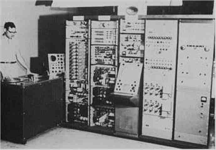
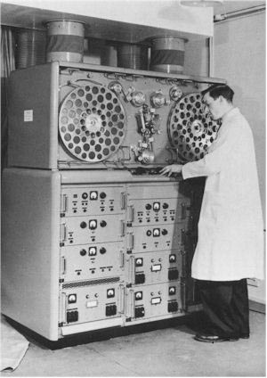
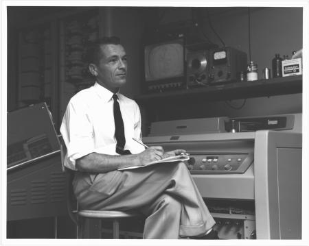
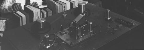
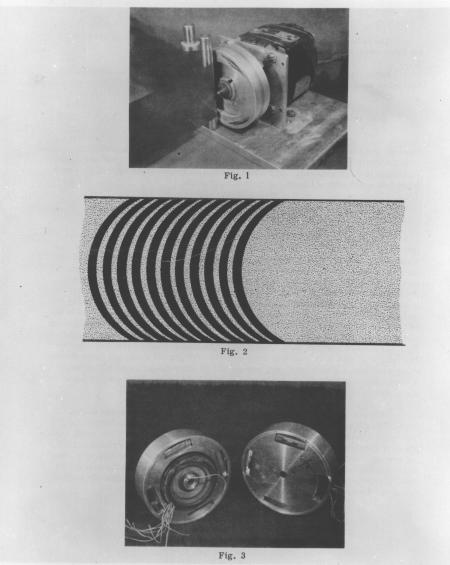
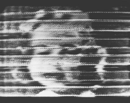
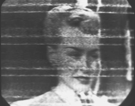
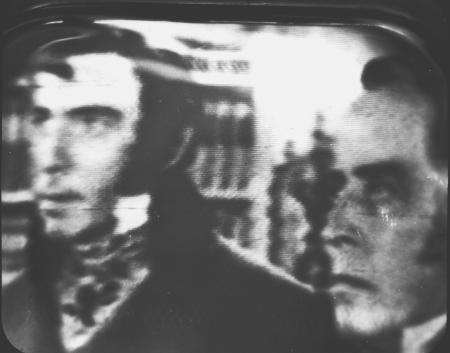
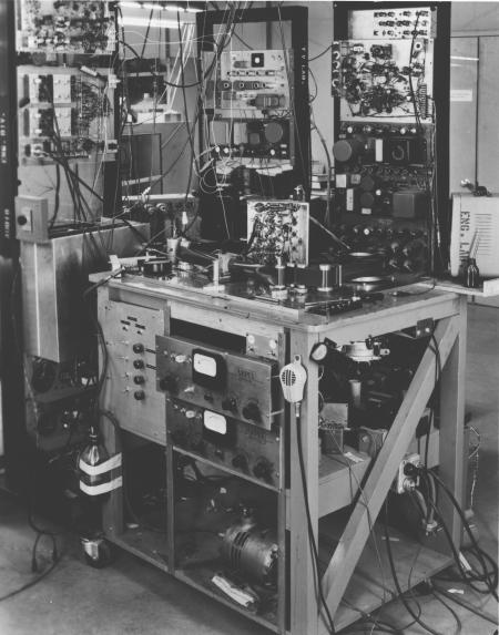
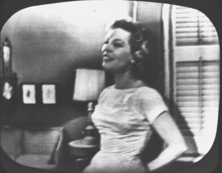
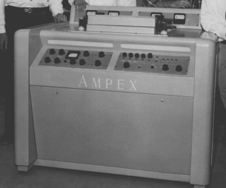
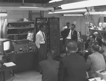
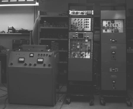
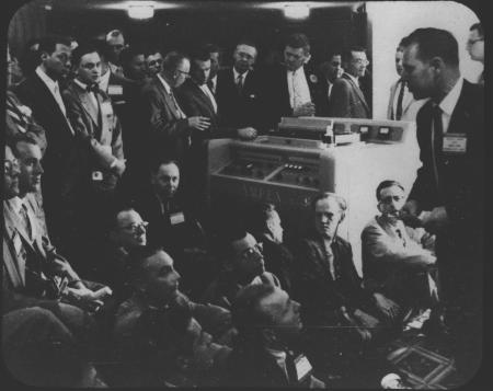
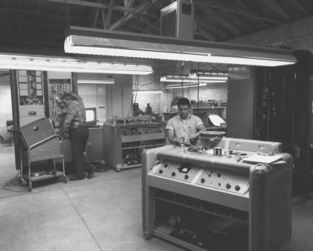
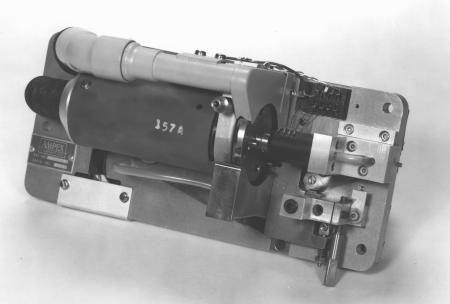
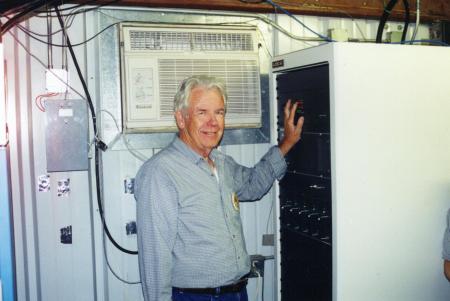
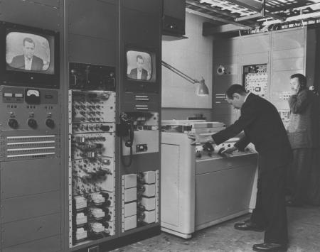
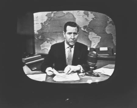
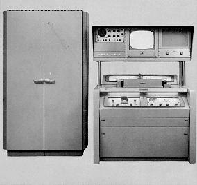
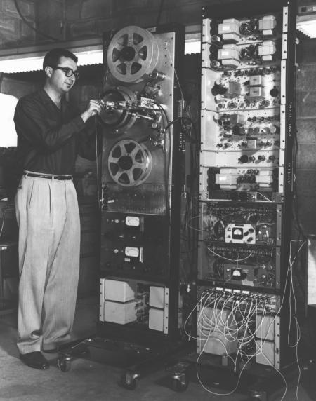
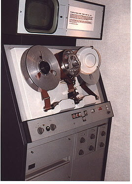
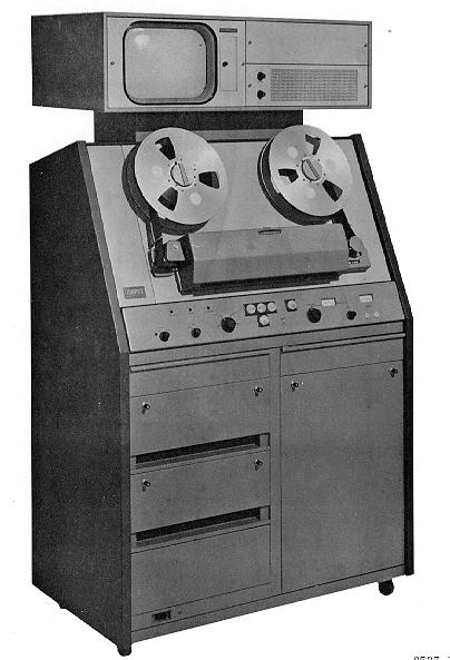
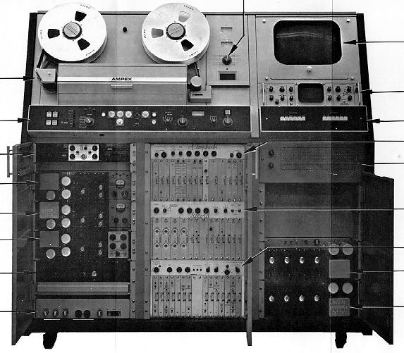
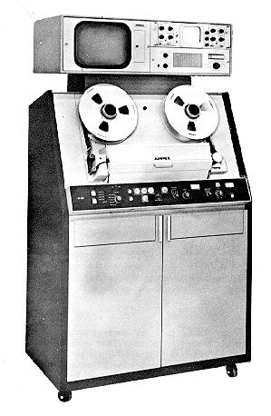